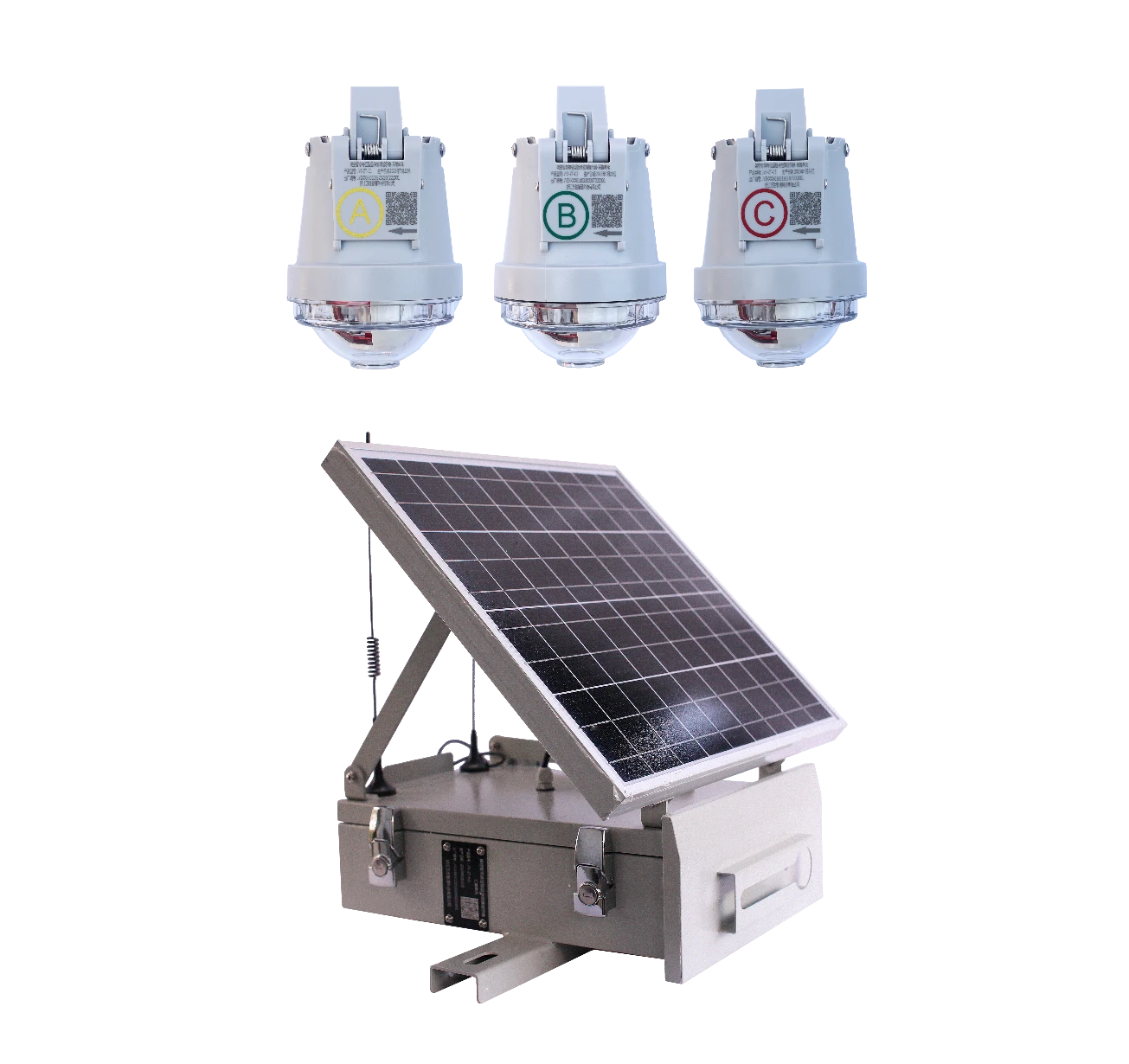
Overhead Transient Characteristic Type Remote Fault Indicator
JYZ-ZT
The JYZ-ZT Transient Characteristic Type Remote Fault Indicator consists of a collection unit and an aggregation unit. The collection unit has the capability of low-power wireless networking, which allows it to upload fault information to the aggregation unit via a local wireless network. Subsequently, the aggregation unit reports the fault information in real-time to the main station positioning system, where the main station processes the information and completes the graphical location display.
Main functions and characteristics

1) High-Resistance Ground Fault Detection: Traditional equipment struggles to detect high-resistance ground faults (such as those caused by tree contact with power lines or deteriorated insulation). However, transient characteristic indicators can achieve highly sensitive detection by analyzing transient signals.

2) Transient Current Analysis: By employing high-frequency sampling technology, these indicators capture the transient current waveforms in the line at the moment a fault occurs and analyze their characteristics to determine the type of fault.

3) Transient Voltage Analysis: Monitor transient voltage changes in the line and combine this information with current signals allows for more accurate fault identification through comprehensive analysis.

4) Fault Section Localization: Multiple indicators working in coordination can precisely locate the section where the fault occurs, narrowing down the area for fault investigation and thus improving the efficiency of fault handling.

5) Fault Data Recording: The indicator can record information such as the time of fault occurrence, type of fault, and magnitude of current, facilitating subsequent analysis and fault diagnosis.

6) Historical Data Query: Maintenance personnel can remotely access historical fault data to analyze the operational status and fault trends of the line.

7) Status Monitoring: The indicator continuously monitors parameters like current and voltage in the line and transmits this data to the monitoring center, enabling maintenance personnel to keep track of the line's operational condition.

8) Remote Configuration: Maintenance personnel can remotely configure the indicator's parameters, such as adjusting the sensitivity of fault detection and setting alarm thresholds.

9) High Sensitivity: Capable of detecting high-resistance ground faults and low-current faults that are difficult for traditional equipment to identify.

Technical parameter
  • 1. Applicable Occasions
    1) Applicable Voltage: 6 - 35 kV
    2) Neutral Grounding Mode: Suitable for various grounding modes
    3) Applicable Conductor Types: Overhead insulated and bare conductors ranging from 35 mm² to 240 mm²
  • 2. Power Supply
    1) Main Power Supply: Line-derived power (10A for full-function operation)
    2) Backup Power Supply: Single-use lithium battery 3.6V, 4Ah/8Ah (optional); Supercapacitor endurance operation time>12 hours
  • 3. Power Consumption
    Static: ≤40 µA
  • 4. Telemetry Accuracy
    Current: 0-100A, Measurement Accuracy: ±3A; 100A - 600A, Measurement Accuracy: ±3%
  • 5. Fault Detection
    1) Identifiable Fault Types: Phase-to-phase short circuit, various types of single-phase ground faults; transient faults and permanent faults
    2) Minimum Reclosing Identification Time: 0.2s
  • 6. Line Status Indication
    1) Indication Type: High-brightness LED, 360° omnidirectional
    2) Continuous Flashing Time After Power Loss: >2000 h
    3) Fault Reset Method: Timed automatic reset, with a time configurable range of 1 to 48 h; automatic reset upon power restoration and remote manual reset
  • 7. Local Communication Method
    1) Frequency Band: 430–480 MHz
    2) Communication Distance: >50 m
    3) Transmission Power Consumption: <25 mA@+10 dBm
    4) Reception Power Consumption: <3 mA
    5) Communication Rate:150 kbps
  • 8. Mechanical Characteristics
    1) Weight: <1Kg
    2) Degree of Protection: IPX7
  • 9. Operating Environment
    1) Operating Temperature: -40°C - 70°C
    2) Humidity: 10% - 100%
  • 10. Service Life
    1) Operating Life: >8 years
    2) Mean Time Between Failures (MTBF) : ≥70 000h
We use cookies to allow our website to function properly, provide social media functionality, and analyze traffic. We also share information with our partners about your use of our website.
Reject
Accept
Submitted successfully
Confirm